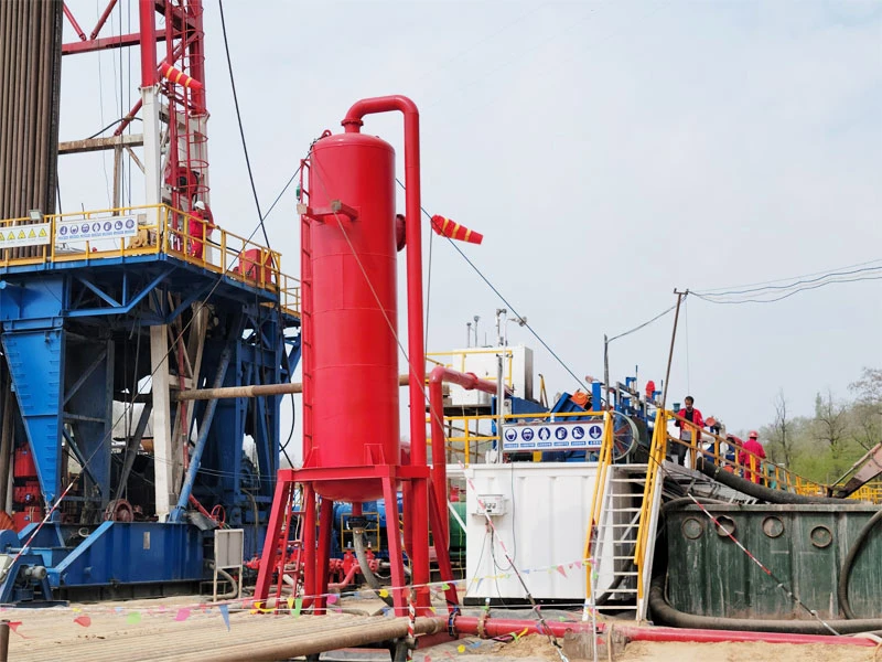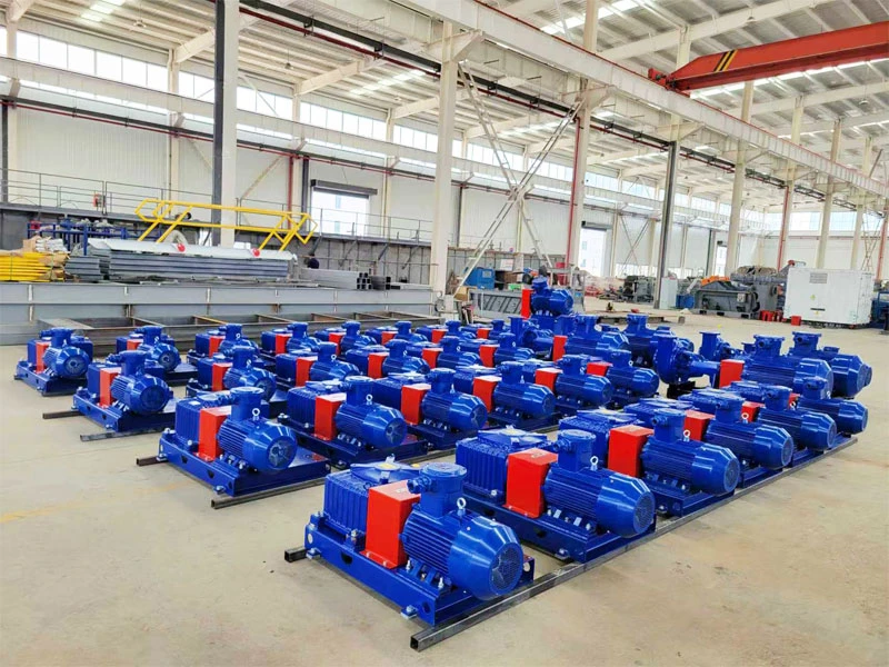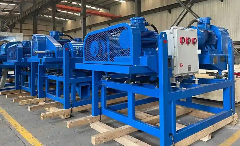
In modern oil and gas drilling, Solids Control Systems (SCS) are critical for maintaining mud integrity. By strategically deploying a multi-stage filtration process, operators can remove harmful drill cuttings while preserving essential weighting agents and chemicals. This ensures the drilling fluid meets the rigorous demands of complex well profiles.
Our high-efficiency 5-stage drilling fluid solids control system workflow ensures superior mud quality and extends equipment longevity.
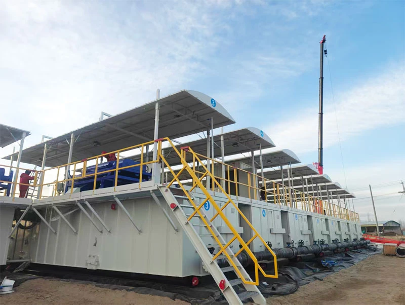
Phase 1: Shale Shaker (Primary Removal)
Target: Large cuttings (>74μm) The process begins when the drilling fluid returns from the wellbore via the flow line. It enters the Shale Shaker, where high-frequency vibration and mesh screens filter out coarse solids. This primary stage is vital for protecting downstream equipment from heavy wear.
Phase 2: Vacuum Degasser (Gas Elimination)
Target: Entrained Air and Gas (H₂S, CO₂, Methane) To prevent “gas-cut” mud, the fluid is processed through a Drilling Fluid Vacuum Degasser. This stage rapidly extracts intrusive gases that could otherwise reduce mud density, compromise hydrostatic pressure, and lead to dangerous well-control issues like blowouts or wellbore instability.
Phase 3: Desander (Coarse Sand Separation)
Target: Sand particles (44μm – 74μm) After primary screening, the mud is pumped into the Desander (typically featuring 10″ or 12″ hydrocyclones). Centrifugal force separates medium-sized abrasive solids that are too fine for the shaker but large enough to damage mud pumps.
Phase 4: Desilter (Fine Particle Separation)
Target: Silt and fine solids (8μm – 44μm) The drilling fluid desilter utilizes a bank of smaller (4″) hydrocyclones to handle finer particles. By removing these silts, the system maintains the ideal plastic viscosity and yield point of the drilling fluid, ensuring efficient hole cleaning.
Phase 5: Decanter Centrifuge (Ultra-Fine Recovery)
Target: Ultra-fine solids (2μm – 8μm) The final stage employs a high-speed Horizontal Decanter Centrifuge. This equipment uses extreme G-forces to separate the smallest harmful solids. This stage is particularly crucial for high-density muds and complex drilling environments, as it allows for the recovery of valuable barite while discarding “dead” solids.
Why Use a 5-Stage System?
While simpler wells may only require 2 or 3 stages, the full 5-stage configuration is the gold standard for complex, deep-water, or high-pressure/high-temperature (HPHT) wells.
- Customization: The workflow is modular; stages can be bypassed or activated based on real-time drilling conditions.
- Cost Efficiency: By maximizing the recycling of clean mud, operators significantly reduce the cost of drilling chemicals and water consumption.
- Compliance: This process ensures the mud properties meet international standards for environmental discharge and drilling performance.
FAQ:
1. What is a 5-stage drilling fluid solids control system, and how does it differ from traditional 3-stage or 4-stage configurations?
A 5-stage solids control system is a comprehensive process flow designed to remove drilled cuttings sequentially after the mud returns to the surface. The typical sequence is: Shale Shaker (1st) → Desander (2nd) → Desilter (3rd) → Decanter Centrifuge (4th) → High-Speed/Fine Centrifuge (5th).
Compared to 3-stage or 4-stage systems, the 5-stage configuration offers superior ultra-fine solids (<5 μm) removal and barite recovery. This significantly reduces density fluctuations, minimizes Non-Productive Time (NPT), and is essential for deep wells, extended-reach drilling (ERD), and high-density fluid systems.
2. What is the primary value of adding the 5th stage (Fine Centrifuge)?
The 5th stage addresses the challenge of colloidal solids control:
- Ultra-fine Removal: It effectively separates 2–5 μm particles, reducing Plastic Viscosity (PV) and Yield Point (YP) to maintain optimal rheological properties.
- Barite Recovery: In high-density fluid systems (Weighted Muds), it separates low-gravity solids (drill cuttings) from barite, maximizing barite recovery and lowering fluid costs.
- Reduced Downhole Risk: By controlling the accumulation of ultra-fine solids, it helps prevent thick filter cakes and differential sticking.
For high-cost deepwater or HPHT wells, the 5th stage typically provides a strong Return on Investment (ROI).
3. Is a 5-stage system necessary for all drilling operations?
No, the applicability depends on well profile, fluid density, and formation characteristics:
- Recommended: Deepwater, HPHT, ERD, and shale gas horizontal wells, particularly those using Oil-Based Mud (OBM) or Synthetic-Based Mud (SBM).
- Optional: Conventional shallow or medium-depth wells with stable formations may find a 4-stage system sufficient.
- Not Recommended: Ultra-shallow or low-budget operations where the capital expenditure (CapEx) and operating expenditure (OpEx) of a 5-stage system cannot be justified by the operational benefits.
A feasibility study considering lithology and fluid chemistry is advised prior to deployment.
4. What are the most common operational mistakes in a 5-stage system?
Field experience highlights several frequent errors:
- Bypassing Stages: Routing fluid directly from the shaker to the centrifuge to save time, which overloads the centrifuge and accelerates wear.
- Incorrect Screen Selection: Using screens that are too fine, resulting in “pooling” (mud bypassing the screen) and reduced processing capacity.
- Improper Centrifuge Settings: Failing to adjust differential speed and bowl speed according to changes in mud weight and solids content.
- Neglecting Chemical Co-treatment: Relying solely on mechanical separation while ignoring the synergy of flocculants and dispersants.
- Poor Maintenance: Ignoring worn centrifuge scrolls or blocked hydrocyclone apexes, which drastically reduces overall system efficiency.
5. How can the performance of a 5-stage system be quantitatively evaluated?
Performance should be tracked using key performance indicators (KPIs):
- Solids Removal Efficiency: Measuring the reduction in Total Suspended Solids (TSS) and Low-Gravity Solids (LGS) from the suction to the discharge line.
- Particle Size Distribution (PSD): Using a laser particle size analyzer to monitor changes in D50 and D90 values across stages.
- Barite Recovery Rate: Analyzing the barite content in the centrifuge underflow versus the overflow.
- Fluid Stability: Tracking the variance in PV, YP, and Gel Strength over time.
- Cost Metrics: Calculating savings on barite consumption, reduced chemical treatment costs, and a decrease in downhole incidents.
Regular reporting of these metrics allows for continuous optimization of the drilling program.