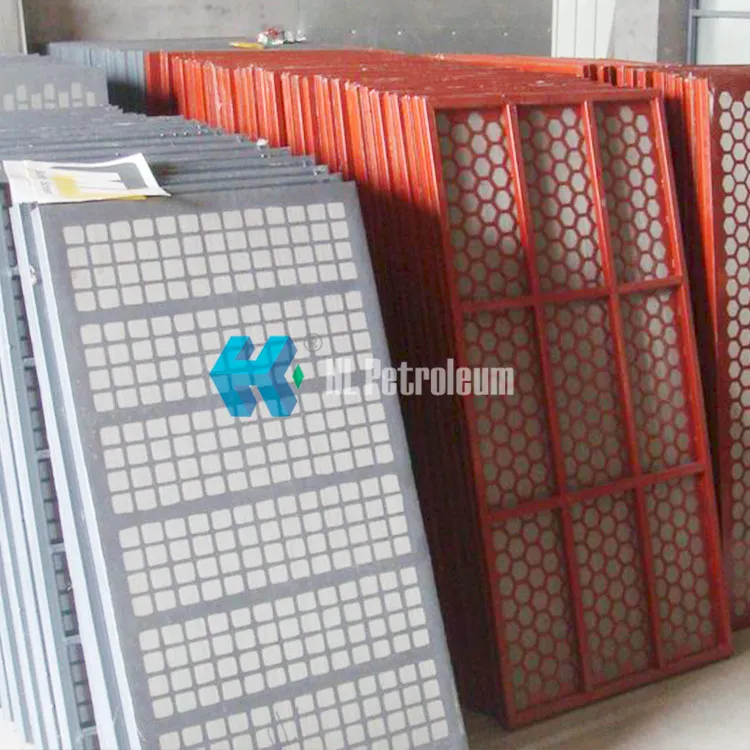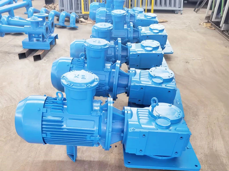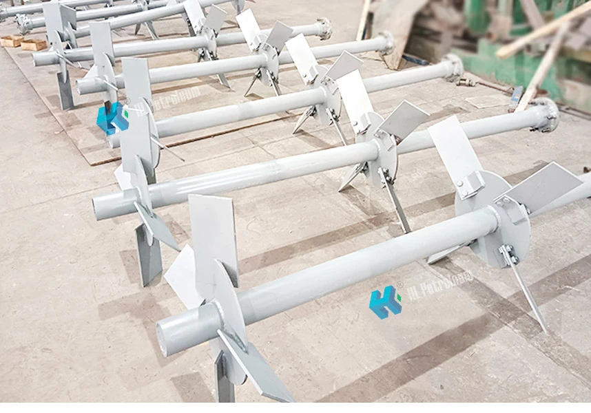
In oil and gas drilling operations, the drilling fluid agitator is critical equipment for ensuring uniform drilling fluid properties and preventing solid phase sedimentation. Its installation quality and routine maintenance directly affect drilling efficiency and operational safety. This article provides a detailed overview of pre-installation inspection, proper installation, lubrication management, safety precautions, and maintenance of drilling fluid agitators, helping field personnel quickly master key operational points.
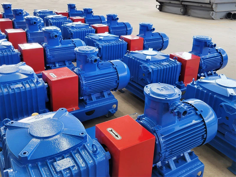
1. Pre-Installation Core Check: Rotation Direction Verification
Before installing the agitator, the rotation direction of the impeller must be confirmed first. This step may seem simple, but it directly impacts agitation performance and equipment service life.
- Correct Rotation Direction: When viewed from the top of the tank, the agitator impeller should rotate in a clockwise direction.
- Direction Indicator: When the rotation direction is incorrect, a directional indicator plate is nailed above the coupling guard. The arrow on the indicator plate must align with the actual rotation direction of the impeller. Installers must verify the arrow direction carefully. If reverse rotation is detected, adjust the motor wiring or drive system promptly—never force start the equipment.
Pro Tip: It is recommended to perform a jog test on the motor before connecting it to the reducer to confirm the rotation direction. This avoids rework and potential damage.
2. Lubrication System Specifications: Reducer Oil Selection and Change Intervals
Drilling fluid agitators typically use worm gear reducers for power transmission. Proper lubrication directly determines the service life of the reducer. The correct oil filling and changing procedures are as follows:
2.1 Lubricant Selection and Filling Volume
- Ambient temperature -30~40℃: Use 220~320# L-CKE/P heavy-duty worm gear oil.
- Ambient temperature 25~65℃: Use 320~460# L-CKE/P heavy-duty worm gear oil.
- Oil Level Standard: The oil level should be within the visible range above the center of the sight glass (red dot)—neither too low nor too high.
- Breather Handling: Before filling, remove the small tapered plug on the breather to ensure internal pressure balance in the reducer and prevent oil leakage or seal damage.
- Filling Volume Reference: The approximate filling volume for each agitator model can be found in the Main Technical Parameters Table. Always refer to this table during initial oil filling.
2.2 Oil Change Intervals and Break-In Management
- First Oil Change: After 100 hours of initial operation, the reducer must be drained, cleaned internally, and refilled with new oil to remove metal particles generated during the break-in period.
- Subsequent Oil Changes: Thereafter, change the oil every 2,500 hours of operation. In harsh working conditions, the interval may be shortened appropriately.
- Oil Change Procedure: Drain the oil when the equipment is shut down and the oil is still warm to ensure complete discharge. Clean the sight glass and breather before adding new oil.
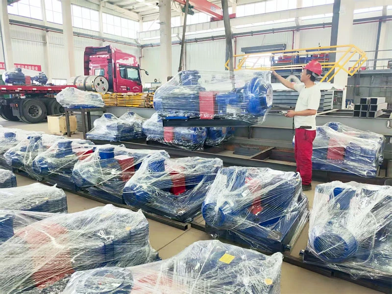
3. Installation Procedure and Key Points
- Foundation Inspection: Check whether the tank installation surface is level and whether embedded bolts or welded bases are secure.
- Equipment Positioning: Hoist the agitator into position smoothly, align bolt holes, and avoid forced hammering.
- Coupling Alignment: Adjust the alignment accuracy between the reducer output shaft and the agitation shaft. Radial deviation and axial clearance must meet manufacturer requirements.
- Fastening and Guarding: Tighten anchor bolts to specified torque, install the coupling guard, and ensure the directional indicator plate on the guard is clearly visible and correctly oriented.
- Auxiliary Component Check: Confirm that agitation blades are securely installed and that no tools or debris remain inside the tank.
4. Safety Precautions: Preventing Personal Injury
When the agitator is running, its blades generate significant torque and rotational speed. Even a minor lapse can cause serious personal injury. The following safety regulations must be strictly observed on site:
- No Approaching During Operation: During agitator operation, operators and related personnel must maintain a safe distance from the tank opening and agitation shaft. Never extend any body part or tool into the tank.
- Power Off Before Maintenance: If inspection, maintenance, or cleaning inside the tank is required, cut off the agitator power supply first, hang a “Do Not Close” warning tag on the control switch, and arrange for a dedicated guardian if necessary.
- Prevent Accidental Startup: When personnel are working inside the tank, no one is allowed to start the agitator under any circumstances to prevent fatal injury from the rotating blades.
- Personal Protective Equipment (PPE): Operators should wear safety helmets, protective goggles, anti-slip gloves, and other labor protection gear. Long hair must be tucked into the hat.
5. Equipment Features and Routine Maintenance
Drilling fluid agitators use worm gear reducer drive transmission, offering the following significant advantages:
- High Torque Transmission: Capable of handling the agitation resistance of high-viscosity drilling fluids.
- Smooth Operation: Worm gear meshing produces low noise and minimal vibration.
- High Agitation Performance: Reasonable impeller design ensures uniform mixing of drilling fluid and prevents sedimentation.
- Reliable Operation: Compact structure with good sealing, adapted to harsh drilling environments.
Routine Maintenance Checklist
- Daily Inspection: Listen for abnormal noise from the reducer, observe whether the oil level on the sight glass is within the normal range, and check for oil leakage at seals.
- Weekly Inspection: Tighten anchor bolts and coupling bolts; clean mud and dust from the equipment surface.
- Monthly Inspection: Check agitation blades for wear; repair or replace if necessary. Verify motor insulation resistance.
- Periodic Oil Change: Strictly follow the schedule of first oil change at 100 hours, then every 2,500 hours thereafter. Use the specified grade of L-CKE/P heavy-duty worm gear oil.
6. Common Faults and Troubleshooting
|
Fault Symptom
|
Possible Cause
|
Corrective Action
|
|---|---|---|
|
Difficulty starting or failure to start
|
Phase loss, burnt motor, seized reducer
|
Check power supply lines, measure motor windings, disassemble reducer to inspect gears/worm
|
|
Excessive reducer temperature
|
Insufficient or degraded lubricant, bearing damage, overloaded operation
|
Supplement or replace lubricant, replace bearings, check if drilling fluid viscosity exceeds standard
|
|
Abnormal vibration or noise
|
Coupling misalignment, deformed blades, loose anchor bolts
|
Re-align, repair or replace blades, tighten bolts
|
|
Oil leakage
|
Worn oil seal, blocked breather, excessive oil level
|
Replace oil seal, clean breather, adjust oil level to standard range
|
Conclusion
Correct installation and standardized maintenance of drilling fluid agitators are fundamental to ensuring stable drilling fluid performance and improving drilling efficiency. Field personnel must keep in mind the three core principles: rotation direction verification, lubrication management, and safe operation. Strictly follow installation procedures and maintenance cycles. Only by getting every detail right can the agitator operate continuously and reliably in harsh drilling environments, safeguarding drilling operations.
Friendly Reminder: This article is compiled based on general technical specifications. For specific operations, please refer to the equipment manufacturer’s instruction manual. For further technical support or spare parts consultation, feel free to contact our professional team.