A drilling fluid mud gas separator is a specialized device for the primary degassing of gas-invaded drilling fluid. It is primarily used to remove large bubbles (approximately 3 to 25 mm in diameter) from gas-invaded drilling fluid. These large bubbles are the expanding gases that fill a certain section of the wellbore annulus and pose a serious threat to drilling.
Working Principle
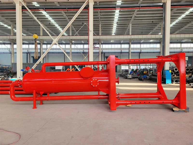
Gas-invaded drilling fluid enters the separator through the separator’s inlet. After colliding with the impact plate, it is dispersed onto a series of internal baffles. These collisions and exposed surface area create turbulent flow, separating the gas from the drilling fluid. Free gas is discharged through the gas outlet at the tank’s top. The exhaust line length is determined and configured on-site. The degassed drilling fluid flows through a shale shaker into a circulation tank.
Figure 1 shows a schematic diagram of the mud gas separator structure. Gas-laden mud ejected from the well passes through the choke manifold’s manifold and enters the cyclone fluid in the upper portion of the separator assembly. Based on the principle of sedimentation, some gas and liquid initially separate. After initial separation, the mud flows through the separator’s separation plates, where the plates disperse it into a thin layer, exposing bubbles on its surface. This further separates the gas and mud. The separator discharges the separated gas from the top through an exhaust pipe to a different location, while the clean mud falls to the bottom and returns to the mud tank through a drain pipe.

liquid level control mechanism
A mechanically controlled valve in the middle of the separator manages the liquid level. It opens and closes the air supply to a pneumatic butterfly valve, ensuring a constant liquid level. This prevents gas-laden mud from entering the mud tank via the drain pipe.
The mechanism uses a float, pressure regulating valve, reversing valve, and connecting rod. When the liquid rises, the float pushes the reversing valve. This sends gas to the butterfly valve, which opens to discharge the liquid. When the liquid drops, the reversing valve reverses, closing the butterfly valve and stopping the discharge.
The main functions of the gas-liquid separator are:
1. It serves as the suction port for oil and gas to enter the multi-stage centrifugal pump;
2. Before the mixed gas enters the multi-stage centrifugal pump, the separator separates free gas from the well fluid, thereby reducing the impact of gas on the operating characteristics of the submersible pump, preventing cavitation and gas lock in the centrifugal pump, and ensuring the normal operation of the multi-stage centrifugal pump. The oil-gas separator is a device that separates crude oil and associated natural gas produced in an oil well. Placed between the submersible centrifugal pump and the protector, it separates free gas from the well fluid. The system feeds liquid to the submersible centrifugal pump, while the tubing and casing annular space releases gas.
We install it on the ground near the No. 1 circulation tank (near the shale shaker). Steel wire ropes secure the separator body to the ground through the four upper corners. An ignition chamber and ignition device sit at the exhaust line outlet.
Before each use, inspect the lower buffer plate. If wear exceeds 10mm, replace both plates simultaneously before re-use.
After each use, drain the drilling fluid from the separator (especially in winter to prevent freezing and cracking of the tank), and open the cleaning port or manhole for thorough cleaning.
 Chat with Engineer