In oil drilling, drilling mud is often called the “lifeblood” of the well. It carries cuttings to the surface, balances formation pressure, stabilizes the wellbore, and cools and lubricates the bit. The deeper the well and the longer the drilling cycle, the more solids build up in the mud. When solids content gets out of control, the problems pile up: rate of penetration drops, mud pumps, bits and drill string wear faster, mud properties deteriorate, and in serious cases you face stuck pipe, lost circulation and other downhole complications that drive up drilling costs.
A solids control system exists to prevent exactly this. But in the field, HL Petroleum has seen that having all the right equipment does not guarantee good results. The sequence and layout of the equipment often matter more than the specifications of any single unit.
This article uses oil drilling as the core scenario and covers two questions: in what order should solids control equipment be arranged, and what details matter when laying it out on the rig site?
1. The Core Principle: Separate by Particle Size, Large to Small
A solids control system works through staged purification. Large particles are removed first, medium particles next, and ultra-fine particles last. Each stage reduces the load on the next. If the order is reversed, downstream equipment clogs, overloads or wears out far faster.
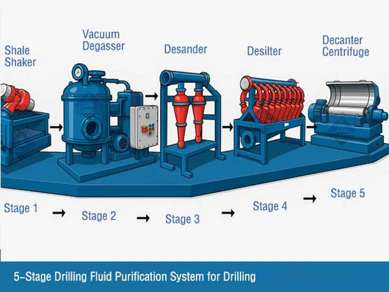
The typical processing sequence in oil drilling is:
Shale Shaker → Degasser → Desander → Desilter (or combined desander/desilter) → Decanter Centrifuge → Storage and Mixing
2. Function and Placement of Each Stage
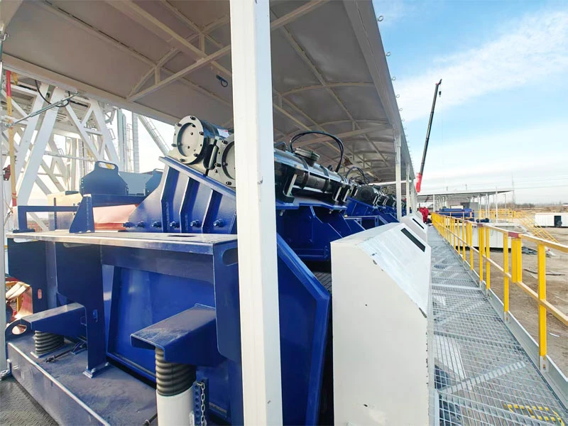
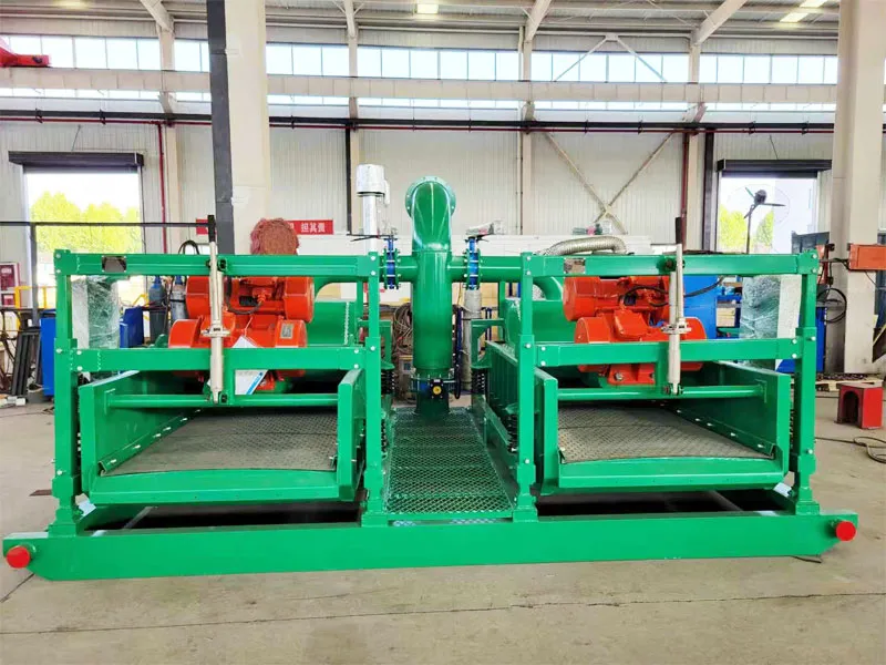
1. Shale Shaker: The First Line of Defense
- Function: Removes large cuttings from the mud returning from the wellbore. It is the first stage and the most critical one.
- Placement:
- Install it directly downstream of the flowline from the wellhead, so the mud reaches the shaker first.
- Set the platform height so screened mud flows by gravity into the next tank.
- Return flow in oil drilling is large, so multiple shakers are usually run in parallel, or equipped with multi-layer screens, to prevent mud from running over the screen surface.
- Tip: Choose screen mesh according to formation and cuttings size. Finer mesh gives higher precision but lower throughput, so balance accuracy against flow rate.
2. Degasser: Standard Equipment in Oil Drilling
- Function: Removes gas entrained in the mud from gas cut, preventing density loss and reduced pump efficiency, and supporting well control safety.
- Placement: After the shale shaker and before the desander. Gas-cut mud entering a hydrocyclone or centrifugal pump causes unstable suction, so degassing must come first.
- Oil drilling carries a high chance of penetrating hydrocarbon-bearing zones, so we do not recommend omitting this stage.
3. Desander: Removing Coarser Solids
- Function: Uses hydrocyclone separation to remove fine sand that passes through the shaker screens.
- Placement:
- Equip it with its own dedicated feed pump. The suction should draw from the tank downstream of the degasser, with the discharge returning to the next tank.
- Its processing capacity should be at least 1.0 to 1.2 times the circulation rate, so all of the mud gets treated.
- Separate the suction tank and discharge tank with an overflow or baffle, so cleaned mud is not drawn back in and short-circuited.
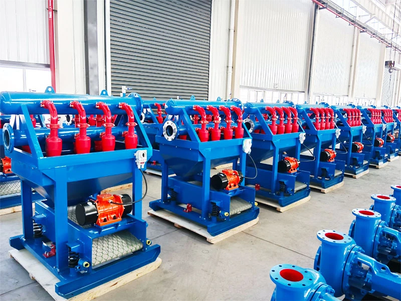
4. Desilter: Removing Finer Particles
- Function: Removes finer silt-sized solids. It is often combined with a fine-mesh shaker (hydrocyclones over a screen deck), and in weighted mud systems it can recover some barite and liquid phase.
- Placement: After the desander, also with its own dedicated feed pump, and with capacity no lower than the circulation rate.
- When space is limited, a combined desander/desilter unit saves room and investment.
5. Decanter Centrifuge: Handling Ultra-Fine Solids and Controlling Mud Cost
- Function: Removes ultra-fine solids that even the desilter cannot handle, controlling sand content and viscosity. In weighted mud systems, it also recovers barite, which noticeably reduces mud material costs.
- Placement:
- Generally the last stage, treating mud downstream of the desilter, or a dedicated portion of the mud.
- The liquid discharge returns to the active tank, and the solids are collected separately for disposal.
- Weighted and unweighted mud call for different operating modes, so adjust according to the mud system.
3. Tank Layout: The Often Overlooked Key
Even excellent equipment will underperform if the tank design is poor.
- Clearly separate the settling, purification and storage tanks. Mud should flow in one direction, from settling to purification to storage, avoiding backflow and cross-contamination.
- Connect the tanks sensibly. The outlet of each tank should connect to the next through an overflow or bottom equalizing valve, so untreated mud cannot mix into cleaned mud.
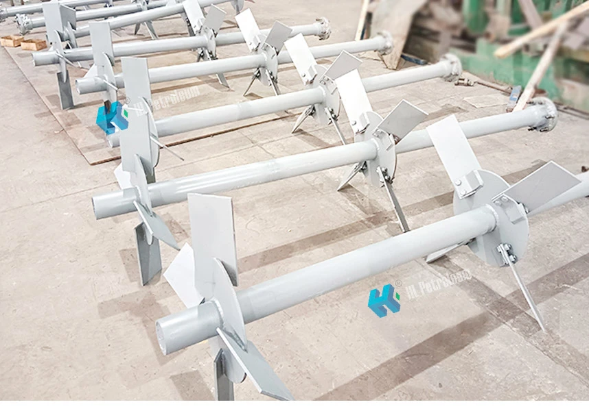
- Install agitators. The suction tanks for the desander and desilter, and the storage tanks, should have agitators to prevent solids from settling. The settling tank, however, should not be strongly agitated.
- Leave room for maintenance and tank cleaning. Keep walkways between tanks for sampling, sand removal and equipment servicing.

4. Practical Layout Advice for Oil Drilling Rig Sites
- Keep the flow straight. Arrange equipment in process order, keep piping short and direct, and minimize elbows to avoid solids settling and blockages in the lines.
- Use elevation differences. The shale shaker sits highest, and gravity carries mud to the downstream tanks, reducing the need for extra lift pumps.
- Use dedicated feed pumps. The desander, desilter and centrifuge should each have their own pump, not shared with the main drilling circulation pumps.
- Make sampling easy. Leave sampling points near the inlet and outlet of each stage so you can check sand content, density and viscosity at any time and adjust promptly.
- Explosion protection and safety. Rig sites carry a risk of flammable gas. Electrical equipment around the shale shaker and degasser must meet explosion-proof requirements and be positioned according to the site’s hazardous area classification.
- Environmental protection. Provide collection measures for solids discharge areas, and store and dispose of cuttings and waste mud in a centralized, compliant way to prevent pollution.
5. Layout Approaches for Different Applications
| Application | Layout Focus |
|---|---|
| Oil Drilling | Use the full five-stage purification chain (shale shaker, degasser, desander, desilter, centrifuge). Drilling cycles are long, circulation volumes are large, and mud performance requirements rise as depth increases, so solids content must be tightly controlled. Formations may contain gas, so a degasser should be standard. With weighted mud, the centrifuge should work together with barite recovery to cut mud costs. Layout must account for rig site space, explosion-proof zoning and ease of maintenance during continuous operation |
| Trenchless (HDD) | Equipment should be compact and easy to transport. Skid-mounted designs are common, integrating shaker, hydrocyclones and centrifuge |
| Piling | Circulation volume and sand content are high, so strengthen the shaker and desander stages |
| Water Well Drilling | Keep equipment simple. A shaker plus a desander meets most needs |
6. Common Layout Mistakes
- Buying equipment without respecting the sequence. Placing the desilter before the desander causes the fine screens to clog frequently.
- Undersized feed pumps. If capacity is below the circulation rate, part of the mud is never treated at all.
- Tank short-circuiting. If the inlet and outlet are too close together, cleaned mud is pulled straight back in, creating an ineffective loop.
- Neglecting routine maintenance. Once screens are damaged or hydrocyclones are worn, the purification performance of the entire system drops noticeably if parts are not replaced promptly.
Conclusion
Oil drilling places high demands on mud quality, which leaves no room for a careless solids control layout. The key to a good arrangement comes down to one sentence: separate by particle size in stages, arrange by flow direction in one direction, and size processing capacity to the circulation rate. The specific design should then be adjusted for formation characteristics, mud system, well depth and rig site space.
If you are planning a solids control system for oil drilling, or want to optimize an existing equipment layout, contact the HL Petroleum technical team. We can provide a configuration and layout recommendation tailored to your well conditions.